The cost impact of not being able to control the quality of welding and repair rates can be substantial. This will and can cost the contractor considerable delay in the completion of the project. Thereafter invoking contractual penalties. Resulting in the loss of profit margins and later arbitration.
Approvals prior to the commencement of welding operations.
Welding Procedure Specifications.
Procedure Qualification Reports.
Welder Certification Certificates.
Welding Consumables.
NDT Company.
NDT Operators.
NDT Procedures.
Radiation Safety.
Post Weld Heat Treatment Company.
Post Weld Heat Treatment Procedure.
Welding Inspection Personnel.
Welding Repair Procedure.
Welding Defects Defined
Defect
Pipe off set mismatch
Cause
Pipe misalignment
Lack of root penetration
Welding technique
Insufficient root fill
Welding technique
Excessive penetration
Welding technique
External undercut
Excessive amps/volts
Internal undercut
Excessive amps/volts
Internal concavity
Welding technique
Root burn through
Welding technique
Lack of root penetration
Weld joint set up
Interpass slag inclusions
Weld technique, grinding, cleaning
Elongated slag inclusions
Weld technique, grinding, cleaning
lack of side wall fusion
Weld technique, amps/volts to low
Interpass cold lap
Weld technique
Scattered porosity
Weld technique
Cluster porosity
Weld technique, insufficient wind cover
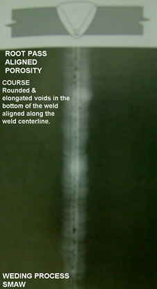
Root pass aligned porosity
Weld technique, insufficient wind cover
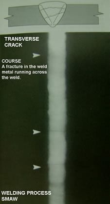
Transverse crack
Insufficient wind cover, lack of pre-heating & post weld heat treatment of weld joint. Material problem.
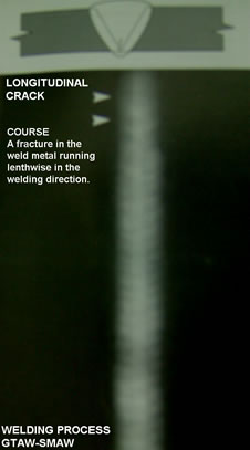
Longitudinal crack
Insufficient wind cover, lack of pre-heating & post weld heat treatment of weld joint. Material problem.
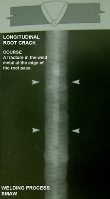
Longitudinal root crack
Insufficient wind cover, lack of pre-heating & post weld heat treatment of weld joint. Material problem.
Tungsten inclusions
Weld technique
Welding Process Metology
Welding Procedures to avoid hydrogen induced cracking.
To control cracking when completing the welding procedure the following factors must be considered.
– Combined thickness of the material to be welded
– Carbon equivalent values
– Hydrogen scales
– Welding arc energy
Codes and Standards That are most Commonly Used on Construction Projects
| ASME Boiler and Pressure Vessel Code | |
| Clause
Power boilers |
Section
I |
| American Pipeline Institute | ||
| API
API AWS ANSI |
1104
650 D1.1 |
Welding Pipelines & related facilities
Welded Steel Tanks for Oil Storage American Welding Society American National Standards Institute |
B31.1 Power Piping
B31.2 Industrial Gas & Air Piping
B31.3 Petrolium Refinery Piping
B31.4 Oil Transportation Piping
B31.5 Refrigeration Piping
B31.6 Chemical Industrial Piping
B31.7 Nuclear Power Piping
B31.8 Gas Transmission & Distribution Piping Systems
Method Statement Welding of Piping and Structural Components
1: Welders shall only work within the limit of their qualification range.
2: Welding supervisor/welders shall ensure that “Welding Procedure Specification” (WPS) selection is taken from the approved matrix for each specific line class/application accompanying each WPS.
3: Withdraw consumables only from designated welding stores and endorse initials on the “Welding Consumables Distribution Form” maintained by the issue clerk.
4: Withdraw only sufficient quantities of welding consumable for a four (4) hour period of work.
5: All low-hydrogen welding electrodes shall be maintained in heated “portable rod caddies”. The lid of the caddie should be closed following the withdrawal of each withdrawal electrodes.
6: Low-hydrogen electrodes shall only be conveyed to the job site in heated “portable rod caddies”.
7: At shift change, all “rod caddies” must be returned to the originating welding store for checking. All issued and unused low-hydrogen electrodes shall be scrapped.
8: The technical requirements of the “Welding Procedure Specification” (WPS) must be followed at all times.
9: Pre-heat and interpass temperatures shall be monitored using “Tempil Stiks” or calibrated “digital” temperature by pyrometers. greater than the nominal wall thickness. ii) For flanges, use the thickness corresponding to two (2) higher wall thickness ranges greater than the nominal wall thickness.
10: Pre-heat values shall be taken calculated and WPS assuming a value of 0.42 CE (Carbon Equivalent). Wall thickness values shall be selected as follows:
a) For pipe-pipe, use the actual wall thickness.
b) For pipe-to-fitting or fitting-to-fitting.
c) For fittings (other than flanges), use the next higher wall thickness range a sufficient period of time to ensure an Oxygen content of less tan 0.5%. When available, “purge monitoring devices” shall be used.
d) Backpurge shall be maintained for a minimum of four (4) passes. Pipe bungs (purge dams) shall be left in place until completion of the joint.
e) The end of partly used filler wire shall be snipped off prior to use.
f) Maintain the tip of the filler rod within the gas shroud during welding to avoid contamination.
g) Interpass temperatures for these materials is critical. The welder shall check the temperature prior to the next pass. All austenitic stainless welds on this project will be tested for “Ferrite” content therefore, cleanliness during fabrication and monitoring of interpass temperatures will have a direct effect on test results.
h) Only approved “iron-free” cutting and grinding disks shall be used.
i) Only approved marking materials (sulphur, chlorine free etc.) are to be used.
j) All material handling devices and equipment shall be adequately protected/lined, to prevent the possibility of carbon “pick-up” (i.e. workbench, transport trucks, supports etc.).
k) Wherever possible, tools shall be colour coded to prevent cross-use with other material types.
11: Pre-head shall be applied through the full thickness of the joint and checked from the opposite side wherever possible.
12: For repair welds, the pre-heating temperature shall be 500 C (1220 F) above that used for the original weld. Maximum pre-heat for repair welding is 1500 C (3020 F).
13: approved WPS. Internal misalignment for butt joints shall not exceed 1.5 mm (1/16”).
14: Deposit the root pass and six (6) successive passes or 1/3 of the weld volume prior to interruption (allowing to cool to ambient temperature).
15: Buttering (build-up) is permitted as follows: a) Buttering shall not exceed the lesser of 10 mm or 1/3 base metal thickness. b) If buttering will exceed 10 mm or 1/3 base metal thickness then this shall be witnessed by the customer and the area shall be tested by PT/MT following completion of buttering but before final welding of the joint.
16: Backwelding is permissible for all applications, so long as the same electrodes and process is used as for the fill pass.
17: The following points shall be observed when fabricating/welding stainless and non-ferrous materials:
a) Weld preps and filler materials shall be degreased using an appropriate solvent.
b) Weld prep surfaces shall be buffered using flapper wheels.
c) Argon hoses shall be checked for any loose connections or leakage etc.
d) Fit up geometry shall be in accordance with the applicable, approved WPS.
e) Bridge tacks to be used. Avoid tacking directly on to the adjacent pipe wall. Bridge tack within the fusion faces of the joint wherever possible.
f) Prior to welding, the backpurge shall be set up in accordance with the approved WPS for a sufficient period of time to ensure an Oxygen content of less tan 0.5%. When available, “purge monitoring devices” shall be used.
g) Backpurge shall be maintained for a minimum of four (4) passes. Pipe bungs (purge dams) shall be left in place until completion of the joint.
h) The end of partly used filler wire shall be snipped off prior to use.
i) Maintain the tip of the filler rod within the gas shroud during welding to avoid contamination.
j) Interpass temperatures for these materials is critical. The welder shall check the temperature prior to the next pass. All austenitic stainless welds on this project will be tested for “Ferrite” content therefore, cleanliness during fabrication and monitoring of interpass temperatures will have a direct effect on test results.
k) Only approved “iron-free” cutting and grinding disks shall be used.
l) Only approved marking materials (sulphur, chlorine free etc.) are to be used.
m) All material handling devices and equipment shall be adequately protected/lined, to prevent the possibility of carbon “pick-up” (i.e. workbench, transport trucks, supports etc.).
n) Wherever possible, tools shall be colour-coded to prevent cross-use with other material types.
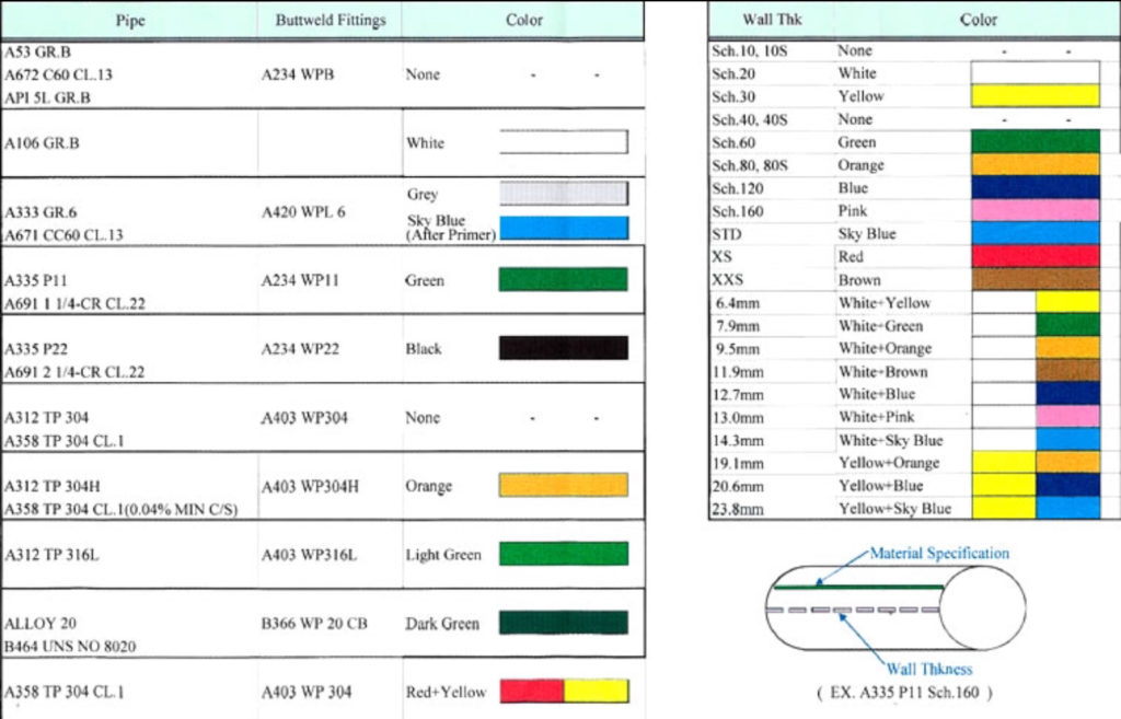
Piping Material Traceability Chart*
*Click to enlarge image
| NDT Technique | Materials applicable | Detection capability | Depth Sizing | Orientation Evaluation | Access problem | Remote Detection | Automated detection |
| Liquid penetrant | All | Surface | No | No | Yes | No | No |
| Ultrasonic | All | Volumetric | Yes | Yes | Limited | Yes | Yes |
| Radiography | All | Volumetric | Yes | Yes | Yes | No | Yes |
| Magnetic Particle | Magnetic | Surface, near-surface | No | No | Yes | No | No |
| Magnetic Fluxleakage | Magnetic | Surface, near-surface | Yes | Yes | No | Yes | Yes |
| Eddy current | Conducting | Surface, near-surface | Yes | yes | Yes | Yes | yes |
| Acoustic Emission | All | Volumetric | Yes | No | No | Yes | Yes |
| Thermo-graphy | All | Surface, near-surface | No | Yes | No | Yes | Yes |
| Visual | All | Surface | No | No | Limited | Yes | Yes |
| XRD | Conducting | Suface Stresses | Yes | No | Yes | No | No |
| Potential drop | Conducting | Surface | Yes | No | Yes | No | Yes |
Engineering and Construction Codes and Standards
ASME IX – American Society of Mechanical Engineers
ASME IX – B 31.3 PROCESS PIPING
ASME IX – B 31.1 POWER PIPING
Material (P numbers) will assist the Welding Engineer to complete the Welding Procedure Specification prior to the mechanical testing of the Procedure Qualification Report.
| P-numbers | Material Composition |
| 1 | Carbon Steel |
| 3 | Up to 1/2% Cr and up to 1/2% Mo |
| 4 | 1 to 2% Cr, 1% Mo Alloy Steel |
| 5A | 2 to 3% Cr, 1% Mo Alloy Steel |
| 5B | 5 to 10% Cr, 1% Mo Alloy Steel |
| 5C | All 5A and 5B Materials heat treated to 85ksi+ |
| 6 | Martensitic Stainless Steel |
| 7 | Ferritic Stainless Steel |
| 8 | Austenitic Stainless Steel |
| 9 | 2 to 5% Ni Alloy Steel |
| 10 | Mn-V, Cr-V, 9%Ni, High Cr Alloy Steels |
| 11 | Low Alloy Steel, Quenched and Tempered to 95ksi+ |
| 21 | 1.2% Mg or Mn alloy Aluminium |
| 22 | 1.2% Mn, 2.5% Mg, 0.25% Cu Aluminium |
| 23 | 1.3% Mg, 0.7% Si, 0.25% Cr Aluminium |
| 25 | 1.5% Mg, 0.8% Mn, 0.15 Cr Aluminium |
| 31 | Copper |
| 32 | Admirally, Naval, Aluminium brass, Muntz Metals |
| 33 | Cu-Si Alloys |
| 34 | Cu-Ni Alloys |
| 41 | Nickel |
| 51 | Titanium |
| 61 | Zirconnium |
Welding Defects
Cold Lap
Cold Lap is a condition where the weld filler metal does not properly with the base metal or the previous weld pass material (interpass cold lap). The arc does not melt the base metal sufficiently and causes the slightly molten puddle to flow into the base material without bonding
Figure 1: Cold Lap
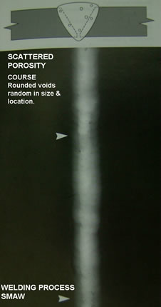
Porosity
Porosity is the result of “gas entrapment” in the solidifying metal. Porosity can take many shapes on a radiograph but often appears as dark round or irregular spots or specks appearing singularly, in clusters, or in rows. Sometimes, porosity is elongated and may appear to have a tail. This is the result of gas attempting to escape while the metal is still in a liquid state and is called “wormhole porosity” All porosity is a void in the material and it will have a higher radiographic density than the surrounding area.
Figure 2: Porosity
Cluster Porosity
Cluster Porosity is caused when flux coated electrodes are contaminated with moisture. The moisture turns into gas when heated and becomes trapped in the weld during the welding process. Cluster porosity appears just like regular porosity in the radiograph but he indications will be grouped close together.
Figure 3: Cluster Porosity
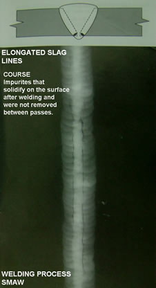
Slag Inclusion
Slag inclusions are non metallic solid material entrapped in weld metal or between weld and base metal. In a radiograph, dark, jagged asymmetrical shapes within the weld or along the weld joints areas are indicative of slag inclusions.
Figure 4: Slag Inclusion
Incomplete Penetration (IP) or lack of penetration (LOP)
Incomplete Penetration (IP) or lack of penetration (LOP) occurs when the weld metal fails to penetrate the joint. It is one of the most objectionable weld discontinuities. Lack of penetration allows a natural stress riser from which a crack may propagate. The appearance on a radiograph is a dark area with well defined, straight edges that follows the land or root face down the center of the weldment.
Figure 5: Incomplete Penetration (IP) or lack of penetration (LOP)
Incomplete fusion
Incomplete fusion is a condition where the weld filler metal does not properly fuse with the base metal. Appearance on radiograph is usually appears as a dark line or lines oriented in the direction of the weld seam along the weld preparation or joining area.
Figure 6: Incomplete fusion
Internal Concavity or Suck Back
Internal concavity or suck back is a condition where the weld metal has contracted as it cools and has been drawn up into the root of the weld. On a radiograph it looks similar to a lack of penetration but the line has irregular edges and it is often quite wide in the center of the weld image.
Figure 7: Internal Concavity or Suck Back
Internal or Root Undercut
Internal or Root Undercut is an erosion of the base metal next to the root of the weld. In the radiographic image it appears as a dark irregular line offset from the centerline of ht weldment. Undercutting is not as straight edged as LOP because it does not follow a ground edge.
Figure 8: Internal or Root Undercut
External or Crown Undercut
External or Crown Undercut is an erosion of the base metal next to the crown on the weld. In the radiograph, it appears as a dark irregular line along the outside edge of the weld area.
Figure 9: External or Crown Undercut
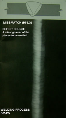
Offset or Mismatch
Offset or Mismatch are terms associated with a condition where two pieces being welded together are not properly aligned. The radiographic image shows a noticeable difference in density between the two pieces. The difference in density is caused by the difference in material thickness. The dark, straight line is caused by the failure of the weld metal to fuse with the land area.
Figure 10: Offset or Mismatch
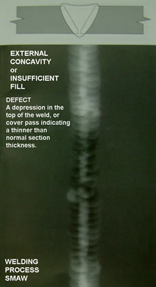
Inadequate Weld Reinforcement
Inadequate Weld Reinforcement is an area of a weld where the thickness of weld metal deposited is less than the thickness of the base metal. It is very easy to determine by radiograph if the weld has inadequate reinforcement, because the image density in the area of suspected inadequacy will be higher (darker) than the image density of the surrounding base material.
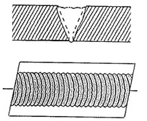
Figure 11: Inadequate Weld Reinforcement
Excess Weld Reinforcement
Excess Weld Reinforcement is an area of a weld that has a weld metal added in excess of that specified by engineering drawings and codes. The appearance on a radiograph is a localized, lighter area in the weld. A visual inspection will easily determine if the weld reinforcement is in excess of that specified by the engineering requirements.
Figure 12: Excess Weld Reinforcement
Cracks
Cracks can be detected in a radiograph only when they are propagating in a direction that produces a change in thickness that is parallel to the x-ray beam. Cracks can appear as jagged and often very faint irregular lines. Cracks can sometimes appear as “tails” on inclusions or porosity.
Figure 13: Cracks
Discontinuities in TIG Welds
Tungsten Inclusion
Tungsten inclusion: Tungsten is a brittle and inherently dense material used in the electrode in tungsten inert gas welding. If improper welding procedures are used, tungsten may be entrapped in the weld. Radio graphically, tungsten is more dense than aluminum or steel, therefore it shows up as a lighter area with a distinct outline on the radiograph
Figure 14: Tungsten Inclusion
Oxide Inclusion
Oxide Inclusions are usually visible on the surface of material being welded (especially aluminum). Oxide inclusions are less dense than the surrounding material, and, therefore appear as dark irregularly shaped discontinuities in the radiograph
Figure 15: Oxide Inclusion
Discontinuities in TIG Welds
Whiskers are short lengths of weld electrode wire, visible on the top or bottom su6rface of the weld or contained within the weld. On a radiograph they appear as light, “wire like” indications.
Burn Through
Burn Through results when too much heat causes excessive weld metal to penetrate the weld zone. Often lumps of metal sag through the weld, creating a thick globular condition on the back of the weld. These globs of metal are referred to as icicles. On the radiograph, burn through appears as dark sports, which are often surrounded by light globular areas (icicles).
Figure 16: Burn Through