- Pressure source and test gauge should be upstream of check valve. If pressure source is downstream, check valve should have flapper removed or jacked?up. (Pressure must be released downstream of check valve after test completion.)
- Ensure that test blinds installed are the Correct thickness. Ensure that all items such as control valves, relief valves, rupture disks, orifice plates, diaphragm instruments, expansion joints, etc., which could be damaged during pressure test have been removed or isolated, as indicated on the pressure test flow diagram. Ensure that equipment, such as filters, which have internals that may be damaged during pressure.
- Ensure that all items such as control valves, relief valves, rupture disks, orifice plates, diaphragm instruments, expansion joints, etc., which could be damaged during pressure test have been removed or isolated, as indicated on the pressure test flow diagram.
- Ensure that equipment, such as filters, which have internals that may be damaged during the pressure test are either blocked from test or that internals have been removed.
- Check all temporary supports that have been called for on the pressure test flow diagrams, piping arrangement drawings or spool drawing to ensure that they have been properly installed.
- Ensure that equipment, such as compressors, which must not be included in the field tests have been properly blocked off with the casing drain open.
- Check open and closed position of all valves.
- Check for proper installation of vents and drains.
- Verify chloride content of test water when testing stainless steels.

Testing
- The pressure test gauge shall normally be located at grade near the test pump.
- Pressure test gauges shall be calibrated to ensure accurate readings. Gauges should be tagged with the date they were last calibrated.
- Care must be exercised not to exceed pressure test specified on the pressure test data.
- When conducting a pneumatic test, it is essential that the contract specification for pneumatic testing be adhered to in order to avoid creating a safety hazard.
- Pneumatic test systems must include double block valves with a bleeder valve between them to safely isolate the pressure source (by closing block valves and opening bleeder to atmosphere) when incremental and final test pressures are attained.
Test Completion
- Care shall be exercised in controlling the rate of draining from vessels in respect to inflow of air through the vent to assure that a vacuum is not applied.
- CAUTION: Prior to commencing drainage, ensure that all vents are open with plugs and blind flanges removed.
- After drainage, remove all temporary blinds and blanks, temporary support, and temporary testing connections.
- Reinstall all items that were removed for test. Ensure that line Specification gaskets and bolts are being used when reinstalling these items.
- Remove all shipping bars from expansion joints.
- Remove Stops from spring hangers and check cold settings.
Why this subject
During hydrotesting and pressure testing operations incidents sometimes happen. This Safety Feedback Notice provides some typical examples which can be used an an aid in highlighting the hazards and dangers involved are what are often seen as routine operations.
Details of 5 incidents
1: Hydro-test of a new vertical vessel
The root cause of the incident is not fully known but there was some thought that hydrotesting with “very cold” water was a contributing factor. Fortunately no injuries occured.

2: Filling of a vertical tank
The filling of the tank was made with water from a fire hydrant. The top the tank blew off becuase the relief valve could not displace the air fast enough for the volume of water that was being pumped in. Fortunately no injury happened, but an operator was on top of the tank a few seconds before.
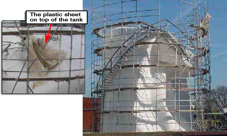
3: Emptying of a vertical tank
The collapse of this tank happened while it was being emptied. A plastic sheet protecting the roof was trapped in the vent; hence a vacuum was caused. There was no injury. It should be noted that this type of incident is not that unusual.
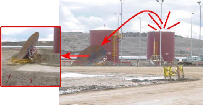
4: Sphere collapse
The accident happened during the filling of a bar 2000 m LPG sphere. Its legs collapsed. One person was killed and one seriously injured.
At the time of the accident, the sphere was approximately 80% full of fresh water.
The vessel’s last hydro-test was 10 years ago and the last inspection of its legs was 5 years ago.
Severe corrosion of the legs under the concrete fire protection was the main cause. The corrosion occurred due to water ingress between the concrete and the steel legs.
The water protective cap located over the concrete was not sufficient to keep water out. After the accident, it was verified that the steel legs had thickness reductions of up to 8mm, with piting holes of up to 10cm .
After analysis and tests, it has been found that the following factors caused the collapse:
- Water caps over the fire-proofing concrete were of poor design thereby letting water penetrate between the steel beams and the concrete.
- Vertical cracks in the concrete let water in.
- Repairs had been done to the concrete, but with poor workmanship.
- The concrete had not adhered to the old concrete, again letting water in.
- The deluge system had been tested with salt water, increasing the possibility of corrosion.

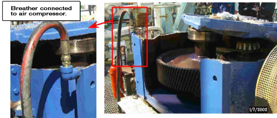
5: Emptying of a gear box
To speeed up the removal of 250l of oil from a gear-box, the guage hole was plugged and the breather was connected to the 6 bar air network.
The gear box exploded, and threw missiles around seriously damaging surrounding piping and structure. Fortunately there was no injury.
SPECIFIC RECOMMENDATIONS
For each case the specific recommendation are generally obvious:
1st incident : Water tempearture is critical when hydro testing. TFE specification (GS PVV 211) states taht both metal and water temperature during pressure testing shall be maintained at least at 16ºC or at least 10ºC above the impact test temperature of the metal.
2nd and 3rd incidents : Venting systems shall be inspected and checked before filling and emptying operations.
4th incident : Is a maintenance problem? Before testing an old vessel, a complete inspection must be performed visually and with NDT. This inspection shall include the vessel, nozzles, appurtenances, and supporting structures.
5th incident : obviously a gear-box is not pressure vessel, but productivity may lead to a risky attitude.